Differences between SLG & SLG Neutral Currents for Transformers & Generators
Description
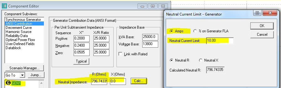
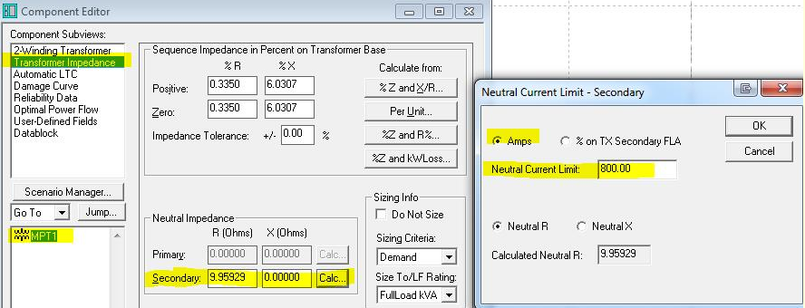
Question: Shouldn’t the Single-Line-to-Ground (SLG) current flowing through the transformer be 800A & 10A for the generator since the Neutral Current Limit was set for both components?
What is the difference between the “InitSymRMS SLG” datablock value and the “InitRMS SLG Neutral” datablock value reported for both Generators & Transformers?
Answer: No, the Neutral Current is not the same as the Single-Line-to-Ground (SLG) current. The Neutral current is the summation of phases A, B, & C. The SLG current is only the highest phase current flowing to the Ground during the phase-to-ground fault. In Balance System Studies, phase A is faulted to ground and therefore Phase A will have the highest current during the fault.
Therefore, “InitSym RMS SLG” value is the highest phase current out of phases A, B, and C during the Phase-to-Ground fault coming out of the generator or Transformer. The “InitRMS SLG Neutral” value is the summation of Phases A, B, & C going through the neutral for the SLG fault.
Please keep in mind that if the license does not have the “Unbalance/Single-Phase” module, then you will not be able to see the individual phase currents reported on the datablock. Users without the UB/Single Phase module should look at the detailed Text Report of the SC study to view individual phase currents. The example attached will show differences using the unbalance short-circuit datablocks and comparing them to Balance Comprehensive Short-Circuit datablocks.
Example:
The Balance System Study – Comprehensive SLG results are showing the following values in Figure 1 for the SLG & the SLGNeutral coming out of the Generator (GEN1) and Transformer (MPT1) for a SLG fault at bus “B2-ABHK:
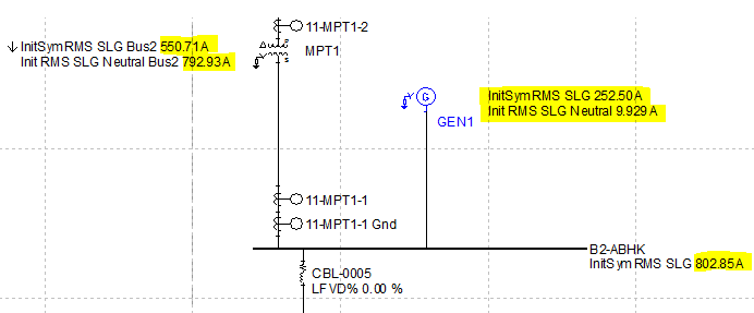
Figure 1: SLG results for fault at bus “B2-ABHK”.
If an Unbalance Single-Phase Short-Circuit study is performed with the same study setup as the Comprehensive Balance System study, then the following results are displayed in Figure 2.
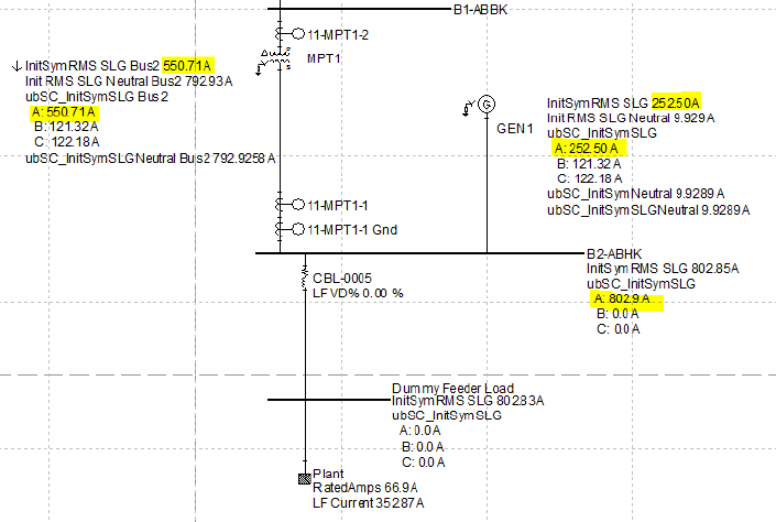
Figure 2: Comprehensive SC & UB SC results for SLG fault at bus “B2-ABHK”.
Notice how datablock “ubSC_InitSymSLG” & “ubSC_InitSymSLG Bus2” is displaying the Phase currents through generator & Transformer respectavily and the highest Phase current is matching the “InitSymRMS SLG” (generator) & “InitSymRMS SLG Bus2” (transformer) datablock values. These values added vectorially is the result SLG value reported at bus “B2-ABHK” for Phase A. Phases B & C at the faulted bus should be zero as shown above.
Now if we change the Datablock Formats “ubSC_initSymSLG Bus2” & “InitSymRMS SLG” to show the SUMMATION of Vectors A, B, & C (Figures 3-4) you will see the following results shown in Figure 5:
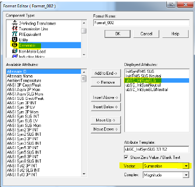
Figure 3: Datablock set to show Vector Summation of Phases A, B, & C.
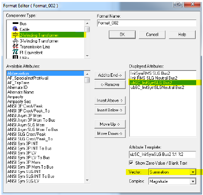
Figure 4: Datablock set to show Vector Summation of Phases A, B, & C.
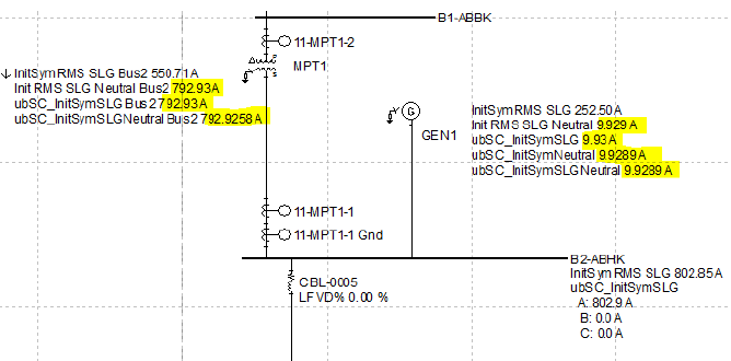
Figure 5: Same Study results, but now showing the Summation of Phase Currents reported by the “ubSC_InitSymSLG” values to show the Neutral Current flowing through the generator/transformer.
Notice how the values reported for generator datablock’s “InitRMS SLG Neutral” is the same as value for “unSC_InitSymSLG” which is summing the phase currents. Also, the same can be said for the Transformer for datablocks “InitRMS SLG Neutral Bus2” & “ubSC_InitSymSLG Bus 2”.
Note: There are cases when the SLG & SLG Neutral currents are the same, but not always. Below (Figure 6) is an example showing the Transformer MPT1 out of service, changing Generator GEN1 to Swing-Bus, and re-running the Balance and Unbalance Comprehensive SC study:
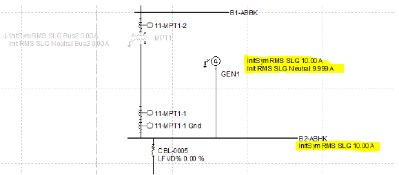
Figure 6: Balance & UB SC results wit Transformer out-of-service & Generator set to Swing-Bus.
Question: Shouldn’t the Single-Line-to-Ground (SLG) current flowing through the transformer be 800A & 10A for the generator since the Neutral Current Limit was set for both components?
What is the difference between the “InitSymRMS SLG” datablock value and the “InitRMS SLG Neutral” datablock value reported for both Generators & Transformers?
Answer: No, the Neutral Current is not the same as the Single-Line-to-Ground (SLG) current. The Neutral current is the summation of phases A, B, & C. The SLG current is only the highest phase current flowing to the Ground during the phase-to-ground fault. In Balance System Studies, phase A is faulted to ground and therefore Phase A will have the highest current during the fault.
Therefore, “InitSym RMS SLG” value is the highest phase current out of phases A, B, and C during the Phase-to-Ground fault coming out of the generator or Transformer. The “InitRMS SLG Neutral” value is the summation of Phases A, B, & C going through the neutral for the SLG fault.
Please keep in mind that if the license does not have the “Unbalance/Single-Phase” module, then you will not be able to see the individual phase currents reported on the datablock. Users without the UB/Single Phase module should look at the detailed Text Report of the SC study to view individual phase currents. The example attached will show differences using the unbalance short-circuit datablocks and comparing them to Balance Comprehensive Short-Circuit datablocks.
Example:
The Balance System Study – Comprehensive SLG results are showing the following values in Figure 1 for the SLG & the SLGNeutral coming out of the Generator (GEN1) and Transformer (MPT1) for a SLG fault at bus “B2-ABHK:
Figure 1: SLG results for fault at bus “B2-ABHK”.
If an Unbalance Single-Phase Short-Circuit study is performed with the same study setup as the Comprehensive Balance System study, then the following results are displayed in Figure 2.
Figure 2: Comprehensive SC & UB SC results for SLG fault at bus “B2-ABHK”.
Notice how datablock “ubSC_InitSymSLG” & “ubSC_InitSymSLG Bus2” is displaying the Phase currents through generator & Transformer respectavily and the highest Phase current is matching the “InitSymRMS SLG” (generator) & “InitSymRMS SLG Bus2” (transformer) datablock values. These values added vectorially is the result SLG value reported at bus “B2-ABHK” for Phase A. Phases B & C at the faulted bus should be zero as shown above.
Now if we change the Datablock Formats “ubSC_initSymSLG Bus2” & “InitSymRMS SLG” to show the SUMMATION of Vectors A, B, & C (Figures 3-4) you will see the following results shown in Figure 5:
Figure 3: Datablock set to show Vector Summation of Phases A, B, & C.
Figure 4: Datablock set to show Vector Summation of Phases A, B, & C.
Figure 5: Same Study results, but now showing the Summation of Phase Currents reported by the “ubSC_InitSymSLG” values to show the Neutral Current flowing through the generator/transformer.
Notice how the values reported for generator datablock’s “InitRMS SLG Neutral” is the same as value for “unSC_InitSymSLG” which is summing the phase currents. Also, the same can be said for the Transformer for datablocks “InitRMS SLG Neutral Bus2” & “ubSC_InitSymSLG Bus 2”.
Note: There are cases when the SLG & SLG Neutral currents are the same, but not always. Below (Figure 6) is an example showing the Transformer MPT1 out of service, changing Generator GEN1 to Swing-Bus, and re-running the Balance and Unbalance Comprehensive SC study:
Figure 6: Balance & UB SC results wit Transformer out-of-service & Generator set to Swing-Bus.
DataImage50.png
DataImage50[1].png
DataImage50[2].png
DataImage34.png
DataImage34[1].png
DataImage34[2].png
DataImage69.png
DataImage6.png